By Grant Laidlaw
Many people ask for assistance in understanding theoretical and practical aspects of the industry. I will endeavour to enlighten. We are going back to basics as I have questions coming in that indicate that the basic understanding necessary to work in industry is not in place.
 |
Grant Laidlaw is currently the owner of the Air Conditioning and Refrigeration Academy (ACRA) in Edenvale. He holds a Bachelor of Business Administration and an associate degree in educational administration. He has a National TechnicalDiploma and completed an apprenticeship with Transnet. He has dual-trades status: refrigeration and electrical. He has been involved with SAIRAC for over two decades and served on the Johannesburg committee as chairman and was also president between 2015 and 2018. Currently he is the SAIRAC national treasurer. |
| Stewart sent in the following: Hi Grant, can you please discuss the automotive side of air conditioning which is often overlooked. The compressors used seem to be different to the rest of industry. These small compressors use wobble plates for capacity control – could you explain how this works? Thank you. |
Variable stroke compressor. All images supplied by Grant Laidlaw
Hi Stewart, yes the compressors used in the automotive sector are quite advanced units. They are for the most part open drive units utilising mechanical seals on the input shaft. There may be an electric clutch on the drive shaft depending on design but let us look into this.
There are various makes and types of compressors used in automotive air-conditioning systems operating on R134a and of late 1234yf. There is some movement into CO2, but this remains somewhat niche. In most cases the compressor internal design could be piston, scroll, wobble plate, variable stroke or vane.
Regardless, all operate as the pump in the A/C system to keep the refrigerant and lubricating oil circulating and to increase the refrigerant pressure from a low-pressure low-temperature vapour to a high-pressure high- temperature vapour.
Basically, all refrigeration compressors serve the same function in the system but how this is achieved differs widely. Let us look at the different types and their basic operation.

Scroll compressor.
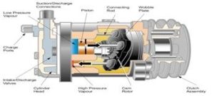
Wobble plate (fixed type)
A reciprocating piston, fixed displacement compressor. The pistons are operated by a wobble plate, which moves them backwards and forwards in the cylinders. As the front shaft turns the wobble plate angle changes, causing the pistons to move in and out, pulling refrigerant vapour in through the suction side, compressing it and discharging this high-pressure vapour into the condenser.

The compression cycle of a scroll compressor.
Scroll type
This compressor uses a unique design with two scrolls, one fixed and one movable, both inter-leaved. The movable spiral is able to orbit or oscillate without actually fully rotating. The movable scroll is connected to the input shaft via a concentric bearing. As the movable spiral oscillates within the fixed spiral, a number of pockets are formed between the spirals. As these pockets decrease in volume the refrigerant is compressed, the pressure and temperature increase, and it is finally discharged through a reed valve at the discharge port in the rear section of the compressor.
The compression cycle is illustrated below. From left to right the low-pressure, low-temperature refrigerant is drawn into the compressor (in blue); and as the compressor scroll orbits the inlet port is closed and the volume of the space containing the refrigerant reduces, compressing the refrigerant (in red).
Finally, the high-pressure refrigerant reaches the discharge port where the refrigerant enters the discharge line to the condenser. Simultaneously, the inlet port opens, allowing low- pressure refrigerant to enter the compressor, repeating the cycle.
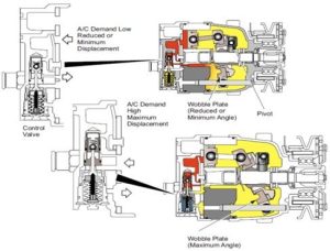
Variable stroke compressor.
Variable stroke
The variable stroke compressor is a variable displacement compressor.
The compressor varies displacement to control capacity to meet A/C system demand at all operating conditions. The compressor features a variable angle wobble plate in five-cylinder axial piston design.
Displacement is controlled by a bellows-actuated control valve located in the rear cylinder head. This control valve senses and responds to the system suction pressure or air-conditioning system demand. Through regulation of the compressor crankcase pressure the wobble plate angle, which determines the length of the piston stroke and therefore compressor displacement, is variable.
To facilitate understanding, when the wobble plate is at a theoretical 90° to the pistons stroke, the actual stroke will be virtually zero and at this point the compressor displacement will be zero. Then the wobble plate is at the maximum angle the displacement is at the compressor’s maximum.
Rotary vane
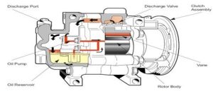
Rotary vane compressors consist of a rotor with three or four vanes and carefully shaped rotor housing. As the compressor shaft rotates, the vanes and housing form chambers. The refrigerant is drawn through the suction port into these chambers, which become smaller as the rotor turns. The discharge port is located at the point where the gas is fully compressed.
Example of a serpentine belt configuration.
The vanes are sealed against the rotor housing by centrifugal force and lubricating oil. The oil sump and oil pump are located on the discharge side, so that the high pressure forces oil through the oil pump, and then onto the base of the vanes keeping them sealed against the rotor housing. During idle, an occasional vane noise from the compressor may be heard. This is due to the time taken for lubricating oil to circulate through the system
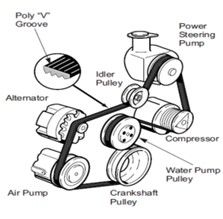
Stewart, the compressors mounting often consists of a bracket to mount the compressor to the engine, a belt idler pulley, compressor drive belt and possibly an extra drive pulley for the crankshaft. The compressor mounting is often manufactured of either plate, cast iron, steel or aluminium; this bracket should exhibit excellent noise absorption qualities especially if using a piston type compressor.
Example of a serpentine belt configuration.
Moving on to the idler pulley, we find a small pulley normally used in conjunction with a belt adjusting mechanism, also used when a belt has a long distance between pulleys to absorb belt vibrations.
Some vehicles do not have an extra pulley to accommodate an A/C drive belt, in which case an extra pulley is bolted onto the existing crankshaft pulley. The most common belt used is the serpentine belt, although V belts are also used.
Stewart, power is transferred from the vehicle primary driver to the air-conditioning compressor via the belts to the drive pulley and compressor clutch mechanism. Some vehicles do not have a clutch fitted, typically on variable capacity compressors.
The clutch is designed to connect the rotor pulley to the compressor input shaft when the field coil is energised. The clutch is used to transmit the power from the engine crankshaft to the compressor by means of a drive belt.
When the clutch is not engaged the compressor shaft does not rotate and refrigerant does not circulate as the rotor pulley free wheels. The field coil is actually an electromagnet – once energized, it draws the pressure plate towards it, locking the rotor pulley and the pressure plate together causing the compressor internals to turn, creating pressure and circulating refrigerant.
Stewart, I hope that this helps with your understanding of the types and basics of operation of an automotive air-conditioning system compressor.
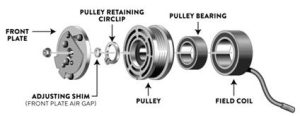
Expanded clutch pack / pulley.
References:
- ACRA
- Classic Auto Air