By Grant Laidlaw
Many people ask for assistance in understanding theoretical and practical aspects of the industry. I will endeavour to enlighten. We are going back to basics as I have questions coming in that indicate that the basic understanding necessary to work in industry is not in place.
 |
Grant Laidlaw is currently the owner of the Air Conditioning and Refrigeration Academy (ACRA) in Edenvale. He holds a Bachelor of Business Administration and an associate degree in educational administration. He has a National TechnicalDiploma and completed an apprenticeship with Transnet. He has dual-trades status: refrigeration and electrical. He has been involved with SAIRAC for over two decades and served on the Johannesburg committee as chairman and was also president between 2015 and 2018. Currently he is the SAIRAC national treasurer. |
| Cayla asks: Grant, could you please look into the use of R744 and how these systems work. It is quite difficult to understand the operation of these systems. Also, a particular concern is the high pressures. Thank you. |
Hi Cayla, yes I can help. In previous RACA issues we looked into CO2 as a refrigerant as well as the critical and triple point. We began looking at subcritical and transcritical systems and what is meant by these terms. Let us continue on this subject by looking at some of the servicing and maintenance aspects as well as explosion prevention.
Installation and maintenance – tooling
Normal refrigeration tools are used with the exception of:
- Refrigerant transfer hoses 120 bar (120MPa)
- CO2 gas detector as part of personal safety equipment
- CO2 leak detector as leak finding instrument
In addition, you will need a digital charging scale suitable for the cylinder weight and sufficiently accurate. Solenoid magnets that are used to manually open solenoid valves, ensuring no refrigerant can be trapped in areas of the system. Trapped refrigerant can cause pressure build up and possible rupture of system components.
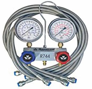
Manifold set: 4-way-recommended 120 bars (120MPa) – subcritical/ transcritical, manifold gauge set with hose lines for CO2. All images supplied by ACRA
Pressure testing
Dry nitrogen is used for the strength test with a suitable high- pressure regulator. A suitable pressure regulator must be used. Failure to do so will result in injury or death. Be aware that there are risks associated with this, especially concerning the test of the high-pressure stage. The test is carried out with 1.43 × PS or with
- × PS and a non-destructive test is executed at 10% of all joints.
- ‘PS’ refers to the manufactured maximum system operating pressure.
- Pressurise slowly and hold pressure for at least 15 minutes.
- Ensure that there is adequate ventilation when releasing nitrogen pressure test charge.
Evacuation
We use the deep evacuation method to evacuate the system. The vacuum required is less than 500 micron using the same evacuation methodology as typical refrigeration systems (HCFCs, HFCs, HCs, etc).
Charging
Charging refrigeration systems utilising R744 is similar to conventional systems, but there are additional insights needed, and some special tools for CO2 (R744) are needed due to the high pressures involved.
Caution: as the pressure of the vacuum is below the triple point, dry ice formation is possible. It is therefore important to fill R744 into a system as a vapour to up to a minimum of 6 bars (600kPa). Note: Some equipment manufacturers recommend 10 bar. Only then is it possible to fill liquid. Typically, a charging scale is used to add refrigerant in accordance with manufacturers’ specifications. Conduct a leak test using a suitable electronic leak detector.
Commissioning
The machine and the function of all safety elements and all electrical equipment has to be tested before operation. The testing process begins with a comparison of the unit specifications and the actual system. Assure whether the documentation is complete: operation manual, maintenance manual, diagrams and electrical drawings.
The next step is inspection of the system:
- The function of the safety relief valves should be tested with dry nitrogen before they are installed. The response value is the maximum allowed pressure PS of the section, for example, suction of intermediate pressure stage is 45 bar (4 500kPa) or for the gas cooler 110 bar (11 000kPa).
- The safety pressure switches are tested through a high- pressure fault. The response value is equal to or less than 0.9 × PS.
The results must be documented in test reports. The following points are a checklist for testing a refrigeration system:
- Inspect all components for any damage
- Check the accordance with the specifications
- Inspect the safety equipment
- Examine the documentation to ensure all necessary
- documents, markings and manuals are there
- Inspect the volume of the receiver
- Check the surface temperature of the piping in public areas
- Compare the specifications and electrical drawings with the actual refrigeration system
- Ensure sufficient power supply
- Inspect the system, whether any vibrations exist
- Inspect the joins, valves and brackets (material, piping run)
- Inspect protection elements against mechanical damage
- Inspect protection of moving parts
- Check insulation (specification, quality and damages)
- Inspect cleanliness of the heat exchanger surfaces
- Provide easy access for maintenance and visual inspection
- Record pressures, temperatures amps in accordance with the commissioning report
Operation
In normal operation the CO2 system has no special features.
One or two regular inspections per year are necessary. The gas cooler and evaporator have to be cleaned periodically. The energy consumption of the motors should be tested regularly.
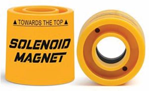
Typical solenoid magnet.
Decommissioning
The CO2 system can be vented to atmosphere or into suitable recovery cylinders. Caution: possible dry ice formation. Venting into recovery cylinders is only possible with subcritical gas phase or if the pressure in the cylinder is higher than 5 600kPa.
Note: With regards to possible recovery, CO2 systems have the handicap that the supply companies generally do not permit the refilling of the CO2 refrigerant cylinders.
Commonly used R744 refrigerant cylinders are equipped with a non-return valve. This is to ensure that the cylinders cannot be refilled which would be otherwise be possible depending on the system pressure. Non-return valves negate the risk of overfilling and contamination of the cylinder with oil. It should be stressed that the recycling of R744 is best carried out by the supplier of the material who will have the necessary product handling and container filling expertise.
For these reasons, as already mentioned, the most logical and viable option is to release it directly into the atmosphere. Keeping in mind that its main risk is asphyxiation due to concentration, we must take the following precautions:
- Always vent it to the outside, directly or through an extraction system. Never release it inside a confined space.
- Even if it is vented to the outside, since CO2 is heavier than air, make sure that it cannot accumulate in low, unventilated areas (pits, basements, etc).
Explosion prevention: The increase of pressure in CO2 systems can especially be a problem if the system is in standstill, for example during a break-down of the system, general switch-off due to maintenance or even when the system pauses during normal operation when enough cooling capacity has been provided. There are two options of handling this, either by supplying an additional cooling system specifically for standstill operation or by limiting the charge size to ensure that the maximum allowable pressure will not be exceeded.
Cooling in standstill: Increase in pressure during standstill can be prevented by installing a small additional (auxiliary) refrigeration system. This usually activates automatically, usually based on pressure readings in the system that indicate standstill during normal operation or breakdowns (emergency cooling) in the system due to different reasons, such as power outages.
The system should be filled with a different refrigerant, such as propane, have a cooling load of about 1kW, and have an evaporation temperature below the triple point of CO2. It should always run on a different power supply. Sub-critical cascade- systems are often equipped with additional cooling units or safety operation functions. The upper stage is activated in case the pressure in the CO2 system exceeds the limit. The charge of the receiver is limited to 80% of the receiver volume.
Limit charge: Smaller, simple single-stage systems can be designed without additional cooling if the design limits the charge size and pressure in the system below a dangerous level.
These systems also do not have safety relief valves. During the design stage, the total volume, or piping and components, refrigerant charge and maximum pressure for expected ambient temperatures is determined. The receiver of such a system must be in the middle or low-pressure stage.
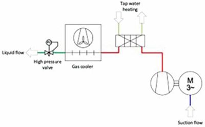
Schematic for a heat revery solution.
Fill factor: The fill factor and the ambient temperature are the deciding factors determining the pressure in the system. This method may be applied only for the receiver or for a simple one stage system. The fill factor is the quotient of the charge mass and complete volume of the system. A system with a volume of 2dm³ and a charge of 560g carbon dioxide has a fill factor of 280kg/m3. If the ambient temperature is 40°C, the expected maximum pressure is 8 000kPa (80 bars). If the filling factor is only 200kg/m-3, the expected maximum pressure is 7 000kPa.
Heat recovery: And finally, we can increase the efficiency of the system utilising heat recovery. Heat recovery is one of most efficient ways to increase the total efficiency of the refrigeration system. Heat recovery systems are used for tap-water heating, space heating or heating a HVAC system. The systems work on the same principles as a system for conventional (HFC) refrigeration systems, HCs and Ammonia (R717).
Cayla, thank you for your question. I hope that this helps with your understanding the use of R744 in refrigeration systems.
References
- ACRA
- The Deutsche Gesellschaft für Internationale Zusammenarbeit GmbH
- ASHRAE
- A-Gas
- Mastercool